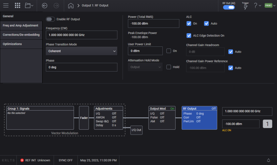
This topic describes the parameters of the RF Output block.
Unless specified as "Bonded," this topic primarily describes capabilities for use when the Configuration is Independent, 2 Tx Coherent, or MIMO. For bonded configurations, do not use SCPI commands described in this topic unless they are specified as "Bonded."
For bonded configurations, be sure to use bonding-supported SCPI commands only. Using unsupported SCPI commands in a bonded configuration will impair the fidelity of the waveform. In these cases, the unsupported SCPI commands are still accepted, but no error or warning is generated.
Some RF Output settings in the General tab vary according to the signal generator model. Use the images below to see these differences. Use the table below to access descriptions for your model.
|
Tab |
M9484C |
|---|---|
| This link opens a separate topic. | |
| This link opens a separate topic. | |
| List/Step Sweep | This link opens a separate topic. |
|
Frequency Center (Remote command only) |
For multi-channel capability only.
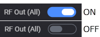
Turns the RF outputs on or off for all the channels in the instrument. This is a master control that gates the individual states. If this control is off, no RF power is emitted from any of the channels; however, the individual channels retain the state of their setting. If this control is on, the RF outputs are on if their individual state is on. To enable or disable individual channels see RF Out.
|
GUI Location |
RF Out (All) |
|
SCPI Command |
[:SOURce]:RFALl:OUTPut[:STATe] ON|OFF|1|0 [:SOURce]:RFALl:OUTPut[:STATe]? |
|
SCPI Example |
RFAL:OUTP OFF RFAL:OUTP? |
|
Preset |
ON |
|
State Saved |
Yes |
|
Choices |
OFF | ON |
|
Initial S/W Revision |
A.01.00 |
Enables or disables the RF output of the indicated channel. To enable or disable all channels, see RF Out (All).
The state of RF Out (All) does not change the RF Out state of a specific channel. For example, if RF Out for Channel 1 is set to on and RF Out (All) is set to off, no power is emitted from the RF Output connector of Channel 1. Likewise, if RF Out for Channel 1 is set to off and RF Out (All) is set to on, no power is emitted from the RF Output connector of Channel 1.
Do not use these SCPI commands for channel bonding. While an error or warning is not generated in this case, the fidelity of the bonded waveform is impaired.
Instead, refer to RF Out (Bonded).
|
GUI Location |
RF Out |
|
SCPI Command |
[:SOURce][:RF<channel>]:OUTPut[:STATe] ON|OFF|1|0 [:SOURce][:RF<channel>]:OUTPut[:STATe]? |
|
SCPI Example |
OUTP ON OUTP? |
|
Notes |
If the M9484APPC or M9484AP1C license is not installed, attempting to set state to ON generates an application error message. |
|
Preset |
OFF |
|
State Saved |
Yes |
|
Choices |
OFF | ON |
|
Initial S/W Revision |
A.01.00 |
|
History |
Added M9484APPC or M9484AP1C at A.09.00 |
Enables or disables the RF output of all physical channels in the bonded set. To enable or disable all channels see RF Out (All).
|
GUI Location |
System Menu > Configure Channels > 2 Channel Bonded > RF Out (bonded-channel icon) |
|
SCPI Command |
[:SOURce]:GROup<group>:CBONded:OUTPut[:STATe] ON|OFF|1|0 [:SOURce]:GROup<group>:CBONded:OUTPut[:STATe]? |
|
SCPI Example |
GRO:CBON:OUTP OFF GRO:CBON:OUTP? |
|
Preset |
OFF |
|
State Saved |
Yes |
|
Range |
OFF | ON |
|
SCPI Change |
[:SOURce]:CBONded<bondingset>:OUTPut[:STATe] ON|OFF|1|0 has been changed to [:SOURce]:GROup<group>:CBONded:OUTPut[:STATe] ON|OFF|1|0. Prior use of :SOUR:CBON:OUTP or :SOUR:CBON1:OUTP is now :SOUR:GRO1:CBON:OUTP. |
|
Initial S/W Revision |
A.07.00 |
|
Modified S/W Revision |
A.10.00 Changed SCPI: Added GROup<group> and removed <bondingset> from :CBONded |
Remote command only.
Sets the power mode of the indicated channel.
Fixed: RF output power is controlled by Power (Total RMS).
List : RF output power is controlled by List/Step Sweep settings.
|
SCPI Command |
[:SOURce][:RF<channel>]:POWer:MODE FIXed|LIST [:SOURce][:RF<channel>]:POWer:MODE? |
|
SCPI Example |
POW:MODE LIST POW:MODE? |
| Couplings |
|
|
Preset |
FIX |
|
State Saved |
Yes |
| Choices | Fixed | List |
| Backward Compatibility SCPI |
N5182B: [:SOURce]:POWer:MODE
|
| Backwards Compatibility Notes |
For N51xxB: Alias [:SOURce]:POWer:MODE SWEep to [:SOURce]:RF1:POWer :MODE LIST Alias [:SOURce][:RF<channel>]:POWer:MODE SWEep to [:SOURce][:RF<channel>]:POWer :MODE LIST |
|
Initial S/W Revision |
A.16.00 |
Controls the RF output power of the indicated channel.
This is the value that the instrument attempts to output. The actual value might be different from the specified value due to the hardware limitations. For example, the output power is different when a high power value is specified with Attenuation Auto off (that is, Attenuation Hold on).
When Power Sweep State is ON, changing the power sets the Power Sweep State to OFF.
|
GUI Location |
RF Output > Amplitude tab > Power (Total RMS) |
|
SCPI Command |
[:SOURce][:RF<channel>]:POWer[:LEVel][:IMMediate][:AMPLitude] <ampl> [:SOURce][:RF<channel>]:POWer[:LEVel][:IMMediate][:AMPLitude]? |
|
SCPI Example |
POW -50 POW? |
| Couplings |
For M9484C with Option 8SG:
|
|
Notes |
The maximum value of this setting is a settable maximum and the datasheet describes actual specified max power that the instruments are capable of. |
|
Dependencies |
When the power is clipped to the User Power Limit the error message "Clipped to User Power Limit" is displayed on the GUI or -222; "Data out of range; Clipped to User Power Limit" to SCPI. |
|
Preset |
-100 dBm |
|
State Saved |
Yes |
|
Min |
For M9484C: -135 dBm |
|
Max |
For M9484C: 20 dBm for all frequencies not covered by these options:
|
|
Resolution |
0.01 dBm |
|
Initial S/W Revision |
A.01.00 |
|
Modified S/W Revision |
A.09.00, A.10.00 |
|
History |
The preset value was changed from -120 dBm at A.03.00 since ALC shows an error with -120 dBm on 20 GHz box. Updated Max at A.03.00. Updated Max at A.09.00. Updated Max for M9484C from 18 dBm to 20 dBm for standard power in A.10.00. |
Power List / Step Sweep
Refer to the sections Power Start and Power Stop in Step Sweep Configuration.
Sets the power into the Device Under Test, the signal at the output of the external combiner. The power calibration, as part of the bonding process, must be performed in order to achieve the specified power level at the output of the combiner. Otherwise the actual power will be reduced by the cable loss and loss through the combiner.
The actual output power available is dependent on the instrument’s output capability and cable and fixture losses.
|
GUI Location |
System Menu > Configure Channels > Bonded > Power (entry field) |
|
SCPI Command |
[:SOURce]:GROup<group>:CBONded:POWer[:LEVel][:IMMediate][:AMPLitude] <ampl> [:SOURce]:GROup<group>:CBONded:POWer[:LEVel][:IMMediate][:AMPLitude]? |
|
SCPI Example |
GRO:CBON:POW 0 GRO:CBON:POW? |
|
Notes |
The maximum value of this setting is a settable maximum and the data sheet describes the actual specified max power that the instruments are capable of. |
|
Dependencies |
When the power is clipped to the User Power Limit the error message "Clipped to User Power Limit" is displayed on the GUI or -222;"Data out of range;Clipped to User Power Limit" to SCPI. |
|
Preset |
-100 dBm |
|
State Saved |
Yes |
|
Min |
-120 dBm |
|
Max |
For M9484C: 21 dBm in all frequencies not covered by these options:
|
|
Resolution |
0.01 dBm |
|
SCPI Change |
[:SOURce]:CBONded<bondingset>:POWer[:LEVel][:IMMediate][:AMPLitude] <ampl> has been changed to [:SOURce]:GROup<group>:CBONded:POWer[:LEVel][:IMMediate][:AMPLitude] <ampl>. Prior use of :SOUR:CBON:POW or :SOUR:CBON1:POW is now :SOUR:GRO1:CBON:POW. |
|
Initial S/W Revision |
A.07.00 |
|
Modified S/W Revision |
A.10.00 Changed SCPI: Added GROup<group> and removed <bondingset> from :CBONded |
Remote command only.
Sets the instrument’s power with the maximum throughput. As the purpose of this command is for speed, there is no limit checking, no coupling, and no update of the value on the front panel. When using this command, there is no inclusion of amplitude offset or amplitude reference. The value is a floating point number in dBm. No error message is raised if the value is clipped.
|
SCPI Command |
FAST<channel>:POWer <double> |
|
SCPI Example |
FAST:POW -50 |
|
Notes |
This command performs no coupling, does not support UP, DOWN, MIN, MAX, DEF. The value is floating point value in dBm; no DB or DBM units are allowed. |
|
State Saved |
No |
|
Min |
For M9484C: -135.0 |
|
Max |
For M9484C: 20 dBm in all frequencies not covered by the options:
|
|
Resolution |
0.01 |
|
Initial S/W Revision |
A.14.00 |
Remote command only.
Sets the instrument’s frequency and power with the maximum throughput. As the purpose of this command is for speed, there is no limit checking, no coupling, and no update of the value on the front panel. When using this command, there is no inclusion of frequency offset, multiplier, frequency reference, amplitude offset, or amplitude reference. The value is an integer frequency in 10 uHz resolution. No error message is raised if the value is clipped.
|
SCPI Command |
FAST<channel>:FP <integer>,<double> |
|
SCPI Example |
FAST:FP 300000000000000,-50 |
|
Notes |
This command performs no coupling, does not support UP, DOWN, MIN, MAX, DEF. The frequency value is an integer in 10 uHz, power value is a double in dBm; no HZ, KHZ, MHZ, GHZ, DB, DBM units are allowed. See Fast Frequency section for details of the frequency setting and Fast Powersection for details of the power setting. |
|
State Saved |
No |
|
Initial S/W Revision |
A.14.00 |
Displays or returns the peak envelope power.
|
GUI Location |
RF Output > Amplitude tab > Peak Envelope Power |
|
SCPI Command |
[:SOURce][:RF<channel>]:POWer:PEPower? |
|
SCPI Example |
POW:PEP? |
|
Initial S/W Revision |
A.01.00 |
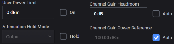
Enables the maximum output power limit set by User Power Limit of the indicated channel.
The value set with this command is not affected by *RST or a power cycle. It is reset to default value with Restore System Defaults.
|
GUI Location |
RF Output > Amplitude tab > User Power Limit |
|
SCPI Command |
[:SOURce][:RF<channel>]:POWer:USER:ENABle ON|OFF|1|0 [:SOURce][:RF<channel>]:POWer:USER:ENABle? |
|
SCPI Example |
POW:USER:ENAB ON POW:USER:ENAB? |
|
Dependencies |
Default value of OFF is set by Restore System Defaults |
|
Preset |
OFF |
|
State Saved |
Persistent, survives preset and power cycle but not saved in the instrument state. |
|
Initial S/W Revision |
A.01.00 |
Sets the maximum output power level for the indicated channel that is lower than the instrument’s normal maximum output power. This affects all modes of power operation. This affects the Amplitude value, but features such as AM may allow the power to exceed the Amplitude value. In other words, this is not a hardware power clamp.
The value is not affected by recall, *RST, Preset or a power-cycle. It is reset to the default value with Restore System Defaults.
|
GUI Location |
RF Output > Amplitude tab > User Power Limit |
|
SCPI Command |
[:SOURce][:RF<channel>]:POWer:USER:MAXimum <ampl> [:SOURce][:RF<channel>]:POWer:USER:MAXimum? |
|
SCPI Example |
POW:USER:MAX 10 POW:USER:MAX? |
|
Dependencies |
Default value of 0 dBm is set by Restore System Defaults |
|
Preset |
0 dBm |
|
State Saved |
No |
|
Min |
For M9484C: -135 dBm |
|
Max |
For M9484C: 20 dBm in all frequencies not covered by these options:
|
|
Resolution |
0.01 dBm |
|
Initial S/W Revision |
A.01.00 |
Enabling attenuation hold (Hold checkbox is marked in the GUI) turns off automatic attenuation and allows you to select one of the following possible RF Output behaviors in the Attenuation Hold Mode drop-down menu.
|
Attenuation Hold Mode |
Description |
Summary |
|---|---|---|
|
Output |
Holds only the output attenuators but allows non-output attenuators to change. Output attenuators are defined as those that, when changed, affect the source match and have the potential to introduce some discontinuity on power changes when not held. They are also distinct in that they are selected based on mode, requested power and frequency only and have no dependency on signal level coming from the DAC. Changing non-output attenuation can result in small discontinuities. |
|
|
All |
Holds all attenuators, avoiding all attenuation-based discontinuities at the cost of dynamic range. |
|
|
GUI Location |
RF Output > Amplitude tab > Attenuation Hold Mode |
|
SCPI Command |
[:SOURce][:RF<channel>]:POWer:ATTenuation:HOLD:MODE OUTPut [:SOURce][:RF<channel>]:POWer:ATTenuation:HOLD:MODE? |
|
SCPI Example |
POW:ATT:HOLD:MODE ALL POW:ATT:HOLD:MODE? |
|
Preset |
OUTPut |
|
Range |
For M9484C Output|All |
|
State Saved |
Y |
|
Initial S/W Revision |
A.12.00 |
Turns the output Attenuator Hold function off or on. When Hold is off (checkbox cleared), auto attenuation is on; when Hold is on, auto attenuation is off. The GUI enables or disables the Hold function, while the SCPI command enables or disables the Auto function. In other words, the GUI and SCPI selections achieve the same result with opposite settings, as outlined in the table below.
|
GUI |
SCPI |
Description |
|---|---|---|
|
|
POW:ATT:AUTO ON |
The attenuator setting is automatically changed as needed to maintain the RF output power level.
|
|
|
POW:ATT:AUTO OFF |
The attenuator remains at its current setting.
|
You can use the Attenuation Hold function to eliminate power level transients that can occur with attenuator switching.
When Attenuation Hold is turned on with User Power Limit on, the output power may exceed the specified power limit because the specified attenuation may not be high enough to achieve the power limit.
|
GUI Location |
RF Output > Amplitude tab > Attenuation [or Attenuation Hold Mode] > Hold |
|
SCPI Command |
[:SOURce][:RF<channel>]:POWer:ATTenuation:AUTO ON|OFF|1|0 [:SOURce][:RF<channel>]:POWer:ATTenuation:AUTO? |
|
SCPI Example |
POW:ATT:AUTO OFF POW:ATT:AUTO? |
| Notes |
For M9484C: Attenuation Auto is On and is not changeable (however, sending the SCPI command does not generate an error.) |
|
Preset (SCPI) |
ON (Attenuation Auto) |
|
Preset (GUI) |
OFF (Attenuation Hold) |
|
State Saved |
Yes |
|
Choices |
OFF | ON |
|
Initial S/W Revision |
A.01.00 |
Enables or disables the automatic leveling control (ALC) circuit on the indicated channel. The purpose of the ALC circuit is to hold output power at a desired level by adjusting the instrument’s power circuits for power drift. Power will drift over time and with changes in temperature.
|
GUI Location |
RF Output > Amplitude tab > ALC On |
|
SCPI Command |
[:SOURce][:RF<channel>]:POWer:ALC[:STATe] ON|OFF|1|0 [:SOURce][:RF<channel>]:POWer:ALC[:STATe]? |
|
SCPI Example |
POW:ALC OFF POW:ALC? |
|
Preset |
For M9484C: ON |
|
State Saved |
Yes |
|
Choices |
OFF | ON |
|
Coupling |
For M9484C: When ALC Auto is On, ALC On/Off changes as follows: ALC On/Off becomes Off when:
Otherwise, ALC becomes On. |
|
Initial S/W Revision |
A.01.00 |
Enables or disables ALC On and ALC - Bandwidth couplings. Setting ALC On or ALC Bandwidth turns this parameter off.
For IQ modulation, the ALC & Power Search should always be set to Auto.
Coupling conditions are described in ALC On and ALC - Bandwidth.
|
GUI Location |
RF Output > Amplitude tab > ALC Auto |
|
SCPI Command |
[:SOURce][:RF<channel>]:POWer:ALC:AUTO ON|OFF|1|0 [:SOURce][:RF<channel>]:POWer:ALC:AUTO? |
|
SCPI Example |
POW:ALC:AUTO OFF POW:ALC:AUTO? |
|
Preset |
ON |
|
State Saved |
Yes |
|
Choices |
OFF | ON |
|
Initial S/W Revision |
A.01.00 |
For M9484C, enables or disables the ALC ignoring pulse edges. When steep slopes are detected in the magnitude, the ALC ignores a small time-window around the steep slope. This allows leveling on only the center portion of pulses and not the edges. If this feature is on, and the signal is not pulsed with a high crest factor, the ALC will intermittently ignore samples, effectively lowering the BW of the ALC loop.
|
GUI Location |
RF Output > Amplitude tab > Edge Detection On |
|
SCPI Command |
[:SOURce][:RF<channel>]:POWer:ALC:EDETect[:STATe] ON|OFF|1|0 [:SOURce][:RF<channel>]:POWer:ALC:EDETect[:STATe]? |
|
SCPI Example |
POW:ALC:EDET OFF POW:ALC:EDET? |
|
Preset |
For M9484C: ON |
|
State Saved |
Yes |
|
Choices |
OFF | ON |
|
Initial S/W Revision |
A.09.00 |
Provided to allow programmatic compatibility with other Keysight Technologies signal generators. Command is accepted but does nothing.
For IQ modulation, the ALC & Power Search should always be set to Auto.
Very Slow – Causes the leveling loop to pass rapidly changing amplitude levels with such as with IQ modulation, but still corrects for slow amplitude drift due to temperature variations or other effects over longer durations of time.Use for CW and most I/Q modulation > 20 GHz (With IQ bandwidths < 200 MHz)
|
GUI Location |
RF Output > Amplitude tab > Bandwidth |
|
SCPI Command |
[:SOURce][:RF<channel>]:POWer:ALC:BANDwidth VSLow|SLOW|MEDium|FAST [:SOURce][:RF<channel>]:POWer:ALC:BANDwidth? |
|
SCPI Example |
POW:ALC:BAND MED POW:ALC:BAND? |
|
Notes |
ALC Bandwidth is VSLow and not changeable, sending the SCPI command does not generate an error. |
|
Preset |
Very Slow |
|
State Saved |
Yes |
|
Choices |
Very Slow |
|
Initial S/W Revision |
A.01.00 |
The table below shows some of the ALC Bandwidth coupling examples.
Remote command only.
Provided to allow programmatic compatibility with other Keysight Technologies signal generators. Command is accepted but does nothing.
|
SCPI Command |
[:SOURce][:RF<channel>]:POWer:ALC:LEVel <ampl> [:SOURce][:RF<channel>]:POWer:ALC:LEVel? |
|
SCPI Example |
POW:ALC:LEV 5 dBm POW:ALC:LEV? |
|
Notes |
Level is -20 dBm and not changeable, sending the SCPI command does not generate an error. |
|
Preset |
-20 dBm |
|
State Saved |
Yes |
|
Min |
-20 dBm |
|
Max |
20 dBm |
|
Resolution |
0.01 |
|
Step |
0.01 |
|
Coupling |
When Attenuation Auto is OFF and Attenuator Compatibility Mode is PSG, the following couplings are defined. When Power is changed or Atten Auto is turned OFF, this value is adjusted to Abs. Power (Power + Offset - Reference) + Atten. When Abs. Power + Atten is smaller than Min and larger than Max, this value is clipped to −20 and 20 with the error messages "Data out of range; ALC Level value clipped to lower limit −20 dBm." and "Data out of range; ALC Level value clipped to upper limit 20 dBm.", respectively. When this value is changed, Abs. Power is adjusted to this value − Atten. |
|
Backwards Compatibility |
[:SOURce]:POWer:ALC:LEVel |
|
Initial S/W Revision |
A.04.00 |
Remote command only.
Provided to allow programmatic compatibility with other Keysight Technologies signal generators. Command is accepted but does nothing.
|
SCPI Command |
[:SOURce][:RF<channel>]:POWer:ALC:SOURce INTernal [:SOURce][:RF<channel>]:POWer:ALC:SOURce? |
|
SCPI Example |
PPOW:ALC:SOUR INT POW:ALC:SOUR |
| Notes | This command is accepted and does not raise an error. |
|
Preset |
INT |
|
State Saved |
Yes |
|
Range |
INT |
|
Backwards Compatibility |
[:SOURce]:POWer:ALC:SOURce |
|
Initial S/W Revision |
A.04.00 |
Applies to M9484C only.
The Channel Gain is the instrument’s digital and analog setup to achieve a particular power with an input, such as a waveform. There are two settings for the Channel Gain: Power Headroom and Power Reference. See Figure: Determining Instrument’s Channel Gain Setup. When Channel Gain Power Headroom Auto is on, the Channel Gain Power Headroom is automatically set to the crest factor (after runtime scaling) of the waveform(s) being played. When Channel Gain Power Reference Auto is on, the Channel Gain Power Reference is the RF Power.
Adjusting the power headroom or power reference allows for selecting a particular setup across a range of powers or for optimizations when the instrument does not know the best optimization point. These settings accomplish the same function as Attenuator Hold in other Keysight Technologies signal generators.
The channel gain power headroom must be at or above the total crest factor of all combined signals, including AWGN and CW interferers, to avoid a DAC overflow. When Auto is on, the system will set this value to the combined crest factors (after runtime scaling). The larger this value is, the less likely that summed signals will run out of power or have an arithmetic overflow, but less dynamic range will be available.
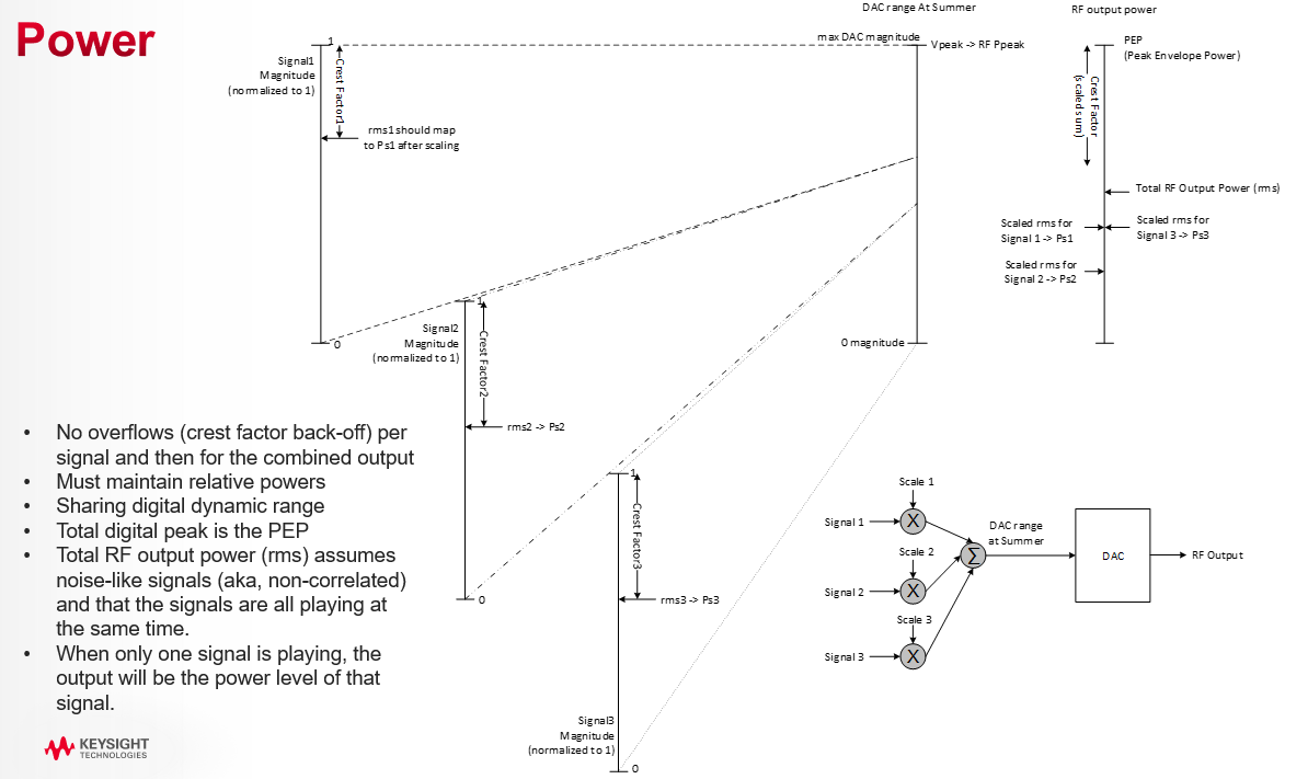
Figure: Power Control with Multiple Signals
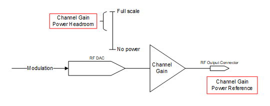
Figure: Determining Instrument’s Channel Gain Setup
See Figure: Power Gain vs Signal Power to understand how a particular signal’s power relates to the static instrument setup set by the channel gain power settings. The headroom sets the amount of digital back-off from full-scale CW. The channel gain reference power Pref sets the optimized gain. These two values determine the maximum peak power. Digital Scale is the dynamic power control applied in the instrument’s DSP to get the appropriate power given the requested power of the signal to play and its crest factors. The crest factors are determined implicitly for internally generated waveforms, or explicitly using the rms of the waveform(s).
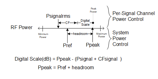
Figure: Power Gain vs Signal Power
The reference headroom sets the amount of digital back-off from full-scale CW. This value must be at or above the total crest factor of all combined signals to avoid overflow. The larger this value is, the less likely that summed signals will run out of power or have an arithmetic overflow, but less dynamic range will be available. See Channel Gain Overview.
|
GUI Location |
RF Output > Amplitude tab > Channel Gain Headroom |
|
SCPI Command |
[:SOURce][:RF<channel>]:POWer:CGAin:HEADroom <rel_ampl> [:SOURce][:RF<channel>]:POWer:CGAin:HEADroom? |
|
SCPI Example |
POW:CGA:HEAD 10DB POW:CGA:HEAD? |
|
Notes |
For values larger than 20 dB, the system may not be capable of delivering maximum specified power. |
|
Dependencies |
When this value is set, Channel Gain Power Headroom Auto is set to off. |
|
Preset |
0 dB |
|
State Saved |
Y |
|
Min |
0 dB |
|
Max |
100 dB |
|
Resolution |
0.01 dB |
|
Initial S/W Revision |
A.12.00 |
When in auto mode, the Power Headroom is the crest factor of the waveform(s) being played, if known. When in CW mode (no modulation), the headroom is 0 dB. See Channel Gain Overview.
|
GUI Location |
RF Output > Amplitude tab > Channel Gain Headroom Auto |
|
SCPI Command |
[:SOURce][:RF<channel>]:POWer:CGAin:HEADroom:AUTO ON|OFF|1|0 [:SOURce][:RF<channel>]:POWer:CGAin:HEADroom:AUTO? |
|
SCPI Example |
POW:CGA:HEAD:AUTO ON POW:CGA:HEAD:AUTO? |
|
Notes |
When this feature is turned off, the automatic values are retained. |
|
Preset |
ON |
|
State Saved |
Y |
|
Initial S/W Revision |
A.12.00 |
This value is the optimized power level for purposes of power control. This follows RF Power when Auto is on. See Channel Gain Overview.
|
GUI Location |
RF Output > Amplitude tab > Channel Gain Power Reference |
|
SCPI Command |
[:SOURce][:RF<channel>]:POWer:CGAin:REFerence <ampl> [:SOURce][:RF<channel>]:POWer:CGAin:REFerence? |
|
SCPI Example |
POW:CGA:REF 0DBM POW:CGA:REF? |
|
Notes |
The maximum value of this setting is a settable maximum and the datasheet describes actual specified max power that the instruments are capable of. |
|
Dependencies |
When the power is clipped to the User Power Limit the error message "Clipped to User Power Limit" is displayed on the GUI or -222;"Data out of range;Clipped to User Power Limit" to SCPI. When this value is set, Channel Gain Power Reference Auto is set to off. |
|
Preset |
-100 dBm |
|
State Saved |
Y |
|
Min |
-135 dBm |
|
Max |
For M9484C: 20 dBm in all frequencies not covered by the options: With Option 1EA: 30 dBm With Option 1EB: 30 dBm With Option 1EC: 30 dBm With Option 1EE: 30 dBm from 9 kHz to 43.5 GHz, 18 dBm above 43.5 GHz |
|
Resolution |
0.01 dBm |
|
Initial S/W Revision |
A.12.00 |
When in auto mode, the Power Reference is the RF Power. See Channel Gain Overview.
|
GUI Location |
RF Output > Amplitude tab > Channel Gain Power Reference Auto |
|
SCPI Command |
[:SOURce][:RF<channel>]:POWer:CGAin:REFerence:AUTO ON|OFF|1|0 [:SOURce][:RF<channel>]:POWer:CGAin:REFerence:AUTO? |
|
SCPI Example |
POW:CGA:REF:AUTO ON POW:CGA:REF:AUTO? |
|
Notes |
When this feature is turned off, the automatic values are retained. This value cannot be set to on when Attenuation Auto is off (that is, Attenuation Hold is on). |
|
Preset |
ON |
|
State Saved |
Y |
|
Initial S/W Revision |
A.12.00 |
Provides a power offset (in dB) to the actual RF output of the indicated channel. This simulates a power level at a test point beyond the RF OUTPUT connector without changing the actual RF output power. The offset value only affects the displayed amplitude setting. You can enter an offset at any time in either normal operation or amplitude reference mode.
|
GUI Location |
RF Output > Amplitude tab > Amplitude Offset |
|
SCPI Command |
[:SOURce][:RF<channel>]:POWer[:LEVel][:IMMediate]:OFFSet <rel_ampl> [:SOURce][:RF<channel>]:POWer[:LEVel][:IMMediate]:OFFSet? [MAXimum|MINimum] |
|
SCPI Example |
POW:OFFS 10 dB POW:OFFS? |
|
Preset |
0 dB |
|
State Saved |
Yes |
|
Range |
-200 to 200 dB |
|
Resolution |
0.01 dB |
|
Initial S/W Revision |
A.01.00 |
Enables or disables the amplitude reference mode for the indicated channel. When the amplitude reference mode is on, subsequent amplitude parameters are set relative to the reference value.
|
GUI Location |
RF Output > Amplitude tab > Amplitude Reference |
|
SCPI Command |
[:SOURce][:RF<channel>]:POWer:REFerence:STATe ON|OFF|1|0 [:SOURce][:RF<channel>]:POWer:REFerence:STATe? |
|
SCPI Example |
POW:REF:STAT ON POW:REF:STAT? |
|
Preset |
OFF |
|
State Saved |
Yes |
|
Choices |
OFF | ON |
|
Initial S/W Revision |
A.01.00 |
Provides an amplitude reference value for the indicated channel.
|
GUI Location |
RF Output > Amplitude tab > Amplitude Reference |
|
SCPI Command |
[:SOURce][:RF<channel>]:POWer:REFerence <ampl> [:SOURce][:RF<channel>]:POWer:REFerence? [MAXimum|MINimum] |
|
SCPI Example |
POW:REF -20 POW:REF? |
|
Preset |
0 dBm |
|
State Saved |
Yes |
|
Range |
-330 to 220 dBm |
|
Resolution |
0.01 dBm |
|
Initial S/W Revision |
A.01.00 |
This immediate action sets the current output amplitude, along with any offset, as a 0 dBm reference value to the indicated channel.
|
GUI Location |
RF Output > Amplitude tab > Set Reference to Current Amplitude |
|
SCPI Command |
[:SOURce][:RF<channel>]:POWer:REFerence:SET |
|
SCPI Example |
POW:REF:SET |
|
Initial S/W Revision |
A.01.00 |
Other Keysight Technologies signal generators provided the ability to adjust the internal attenuators and amplifiers for coarse tuning and modulation scaling for fine tuning. The Power Search SCPI commands are provided to allow programmatic compatibility with those instruments.
Remote command only.
Provided to allow programmatic compatibility with other Keysight Technologies signal generators. This command is accepted but does nothing.
|
SCPI Command |
[:SOURce][:RF<channel>]:POWer:ALC:SEARch ON|OFF|1|0|ONCE [:SOURce][:RF<channel>]:POWer:ALC:SEARch? |
|
SCPI Example |
POW:ALC:SEAR OFF POW:ALC:SEAR? |
|
Notes |
For M9484C: This command is accepted and does not raise an error. |
|
Preset |
ON |
|
State Saved |
Yes |
|
Choices |
ON | OFF | ONCE |
|
Initial S/W Revision |
A.01.00 |
Remote command only.
Provided to allow programmatic compatibility with other Keysight Technologies signal generators. Command is accepted but does nothing.
|
SCPI Command |
[:SOURce][:RF<channel>]:POWer:ALC:SEARch:IMMediate [:SOURce][:RF<channel>]:POWer:ALC:SEARch:IMMediate? |
|
SCPI Example |
POW:ALC:SEAR:IMM POW:ALC:SEAR:IMM? |
|
Notes |
This command is accepted and does not raise an error. The Search query returns 0. |
|
State Saved |
No |
|
Initial S/W Revision |
A.02.00 |
Remote command only.
Provided to allow programmatic compatibility with other Keysight Technologies signal generators. Command is accepted but does nothing.
|
SCPI Command |
[:SOURce][:RF<channel>]:POWer:ALC:SEARch:OFFSet <rel_ampl> |
|
SCPI Example |
POW:ALC:SEAR:OFFS -10 |
|
Notes |
This command is accepted and does not raise an error. |
| Preset | 0 |
|
State Saved |
No |
|
Initial S/W Revision |
A.02.00 |
Tap or click within this area of the GUI to access the Frequency and Amplitude Adjustment Setup screen, where you can configure these parameters. Once you complete your configuration, click or tap Back and this area updates to reflect your custom configuration.
Remote command only.
Sets the frequency mode of the indicated channel.
CW: RF Output frequency is fixed to Frequency (CW).
LIST: RF Output frequency is controlled by List / Step Sweep settings.
|
SCPI Command |
[:SOURce][:RF<channel>]:FREQuency:MODE CW|LIST [:SOURce][:RF<channel>]:FREQuency:MODE? |
|
SCPI Example |
FREQ:MODE CW FREQ:MODE? |
| Couplings |
|
|
Preset |
CW |
|
State Saved |
Yes |
|
Choices |
CW|List |
| Backwards Compatibility SCPI |
N51xxB: [:SOURce]:FREQuency:MODE |
| Backwards Compatibility Notes |
For N51xxB: Alias [:SOURce]:FREQuency:MODE FIXed to [:SOURce]:RF1:FREQuency:MODE CW Alias [:SOURce]: FREQuency:MODE SWEep to [:SOURce]:RF1:FREQuency:MODE LIST Alias [:SOURce][:RF<channel>]:FREQuency:MODE FIXed to [:SOURce][:RF<channel>]:FREQuency:MODE CW Alias [:SOURce][:RF<channel>]:FREQuency:MODE SWEep to [:SOURce][:RF<channel>]:FREQuency:MODE LIST |
|
Initial S/W Revision |
A.16.00 |
Controls the output frequency of the indicated channel.
When Vector Modulation is on, this is the center of the modulation frequency.
When Frequency List/Step Sweep is on, changing the frequency sets the Frequency List/Step Sweep off.
Do not use these SCPI commands for channel bonding. While an error or warning is not generated in this case, the fidelity of the bonded waveform is impaired.
Instead, refer to Frequency (CW) (Bonded).
|
GUI Location |
RF Output > Frequency and Phase tab > Frequency (CW) |
|
SCPI Command |
[:SOURce][:RF<channel>]:FREQuency[:CW] <freq> [:SOURce][:RF<channel>]:FREQuency[:CW]? |
|
SCPI Example |
FREQ 3 GHZ FREQ? |
| Couplings |
For M9484C with Option 8SG:
|
|
Preset |
1 GHz |
|
State Saved |
Yes |
|
Min |
For M9484C = 9 kHz |
|
Max |
For M9484C: With Option 506 = 6 GHz With Option 508 = 8.5 GHz With Option 514 = 14 GHz With Option 520 = 21.6 GHz With Option 532 = 31.8 GHz With Option 544 = 44 GHz With Option 554 = 54 GHz With Option AL2 and V3080A-F06 connected = 67 GHz With Option AL2 and V3080A-F07 connected = 75 GHz With Option AL2 and V3080A-F09 connected = 90 GHz With Option AL2 and V3080A-F11 connected = 110 GHz |
| Unavailable Range |
For M9484C: When Option AL2 and V3080A with any upconverter option connected:
|
|
Resolution |
For M9484C: 0.00001 Hz |
|
Backwards Compatibility SCPI |
N51xxB: [:SOURce]:FREQuency:FIXed |
|
Backwards Compatibility Notes |
For N51xxB: Alias [:SOURce]:FREQuency:FIXed to [:SOURce]:RF1:FREQuency[:CW] Alias [:SOURce][:RF<channel>]:FREQuency:FIXed to [:SOURce][:RF<channel>]:FREQuency[:CW] |
|
Initial S/W Revision |
A.01.00 |
|
Modified S/W Revision |
A.03.00, A.07.00, A.09.00, A.11.00 |
|
History |
Added the max value for Option F14/F20 at A.03.00 Added M1749A at A.07.00 Added M9484C at A.09.00 Added M9484C-AL2 and V3080A at A.11.00 |
Sets the frequency directed to the Device Under Test; the signal at the output of the external combiner.
|
GUI Location |
System Menu > Configure Channels > Bonded > Frequency (entry field) |
|
SCPI Command |
[:SOURce]:GROup<group>:CBONded:FREQuency[:CW] <freq> [:SOURce]:GROup<group>:CBONded:FREQuency[:CW]? |
|
SCPI Example |
GRO:CBON:FREQ 18 GHZ GRO:CBON:FREQ? |
|
Dependencies |
UP and DOWN are based on Bonded Frequency Increment Step |
|
Preset |
1 GHz |
|
State Saved |
Yes |
|
Min |
1 MHz |
|
Max |
For M9484C: With Option 506 = 3.5 GHz With Option 508 = 5.5 GHz With Option 514 = 11.5 GHz With Option 520 = 19.1 GHz With Option 532 = 29.5 GHz With Option 544 = 41.5 GHz With Option 554 = 51.5 GHz |
|
Resolution |
0.01 Hz |
|
SCPI Change |
[:SOURce]:CBONded<bondingset>:FREQuency[:CW] <freq> has been changed to [:SOURce]:GROup<group>:CBONded:FREQuency[:CW] <freq>. Prior use of :SOUR:CBON:FREQ or :SOUR:CBON1:FREQ is now :SOUR:GRO1:CBON:FREQ. |
|
Initial S/W Revision |
A.07.00 |
|
Modified S/W Revision |
A.10.00 Changed SCPI: Added GROup<group> and removed <bondingset> from :CBONded |
Remote command only.
Controls the incremental step value of the indicated channel for the Frequency CW or Fixed parameters. The value set with this command is not affected by *RST or a power cycle. It is reset to the default value with Restore System Defaults.
Do not use these SCPI commands for channel bonding. While an error or warning is not generated in this case, the fidelity of the bonded waveform is impaired.
Instead, refer to Frequency Increment (Bonded).
|
SCPI Command |
[:SOURce][:RF<channel>]:FREQuency[:CW]:STEP[:INCRement] <freq> [:SOURce][:RF<channel>]:FREQuency[:CW]:STEP[:INCRement]? [MAXimum|MINimum] |
|
SCPI Example |
FREQ:STEP 100 MHZ FREQ:STEP? |
|
Dependencies |
Default value of 100 kHz is set by Restore System Defaults |
|
Preset |
Not changed by Preset |
|
State Saved |
No |
|
Min |
For M9484C: 0.00001 Hz |
|
Max |
99 GHz |
|
Range |
0.01 Hz to 99 GHz |
|
Resolution |
For M9484C: 0.00001 Hz |
|
Initial S/W Revision |
A.01.00 |
|
Modified S/W Revision |
A.09.00 |
|
History |
Added M9484C at A.09.00 |
Remote command only.
Controls the incremental step value of the indicated bonding set for the Frequency parameters. The value set with this command is not affected by *RST or a power cycle, is it reset to default value with Restore System Defaults.
|
SCPI Command |
[:SOURce]:GROup<group>:CBONded:FREQuency[:CW]:STEP[:INCRement] <freq> [:SOURce]:GROup<group>:CBONded:FREQuency[:CW]:STEP[:INCRement]? [MAXimum|MINimum] |
|
SCPI Example |
GRO:CBON:FREQ:STEP 100 MHZ GRO:CBON:FREQ:STEP? |
|
Dependencies |
Default value of 100 kHz is set by Restore System Defaults |
|
Preset |
100 kHz |
|
State Saved |
Persistent, survives preset and power cycle but not saved in the instrument state. |
|
Min |
0.02 Hz |
|
Max |
99 GHz |
|
Resolution |
0.02 Hz |
|
SCPI Change |
[:SOURce]:CBONded<bondingset>:FREQuency[:CW]:STEP[:INCRement] <freq> has been changed to [:SOURce]:GROup<group>:CBONded:FREQuency[:CW]:STEP[:INCRement] <freq>. Prior use of :SOUR:CBON:FREQ:STEP or :SOUR:CBON1:FREQ:STEP is now :SOUR:GRO1:CBON:FREQ:STEP. |
|
Initial S/W Revision |
A.07.00 |
|
Modified S/W Revision |
A.10.00 Changed SCPI: Added GROup<group> and removed <bondingset> from :CBONded |
Remote command only.
Sets the instrument’s frequency with the maximum throughput. As the purpose of this command is for speed, there is no limit checking, no coupling, and no update of the value on the front panel. When using this command, there is no inclusion of frequency offset, multiplier, or frequency reference. The value is an integer frequency in 10 uHz resolution. No error message is raised if the value is clipped.
|
SCPI Command |
FAST<channel>:FREQuency <integer> |
|
SCPI Example |
FAST:FREQ 300000000000000 |
|
Notes |
This command performs no coupling, does not support UP, DOWN, MIN, MAX, DEF. The value is an integer in 10 uHz; no HZ, KHZ, MHZ, GHZ units are allowed. |
|
State Saved |
No |
|
Min |
For M9484C 900000000 |
|
Max |
For M9484C:
|
|
Resolution |
10 uHz |
|
Initial S/W Revision |
A.14.00 |
Phase Transition Mode pertains to the M9484C VXG with Option PCH.
This control selects the behavior of the phase across frequency changes.
Transition Mode of Continuous attempts to minimize spectral splatter on frequency transitions by maintaining the same phase across the point of the switch.
Transition Mode of Coherent causes the instrument to act as if all frequencies were generated by independent transmitters that are pulsed on and off; resulting in the phase of any given frequency will always reflect the same phase ramp over time, even if the source has changed to other frequencies in between.
Undefined means that the phase transition has no guaranteed phase behavior.
Reset will reset the phase to the Phase Offset on any frequency change.
For M9484C only: Multi-channel Coherent (MCOHerent) is a variant of Coherent where the phase of all channels is determined by a constant phase ramp over time utilizing a common frequency; frequency changes that don’t result in a path change will maintain the same phase relationship between channels. The amount of center frequency change must be within the bandwidth limits of the channel, e.g. with option R25, a frequency change of 500-1000 MHz (without path hold).
|
GUI Location |
RF Output > Frequency and Phase tab > Phase Transition Mode |
|
SCPI Command |
[:SOURce][:RF<channel>]:PHASe:MODE CONTinuous|COHerent|UNDefined|RESet|MCOHerent [:SOURce][:RF<channel>]:PHASe:MODE? |
|
SCPI Example |
PHAS:MODE CONT PHAS:MODE? |
|
Notes |
For M9484C without Option PCH, the value is Continuous and not changeable. Error message raised if user attempts to set value to HW that doesn’t provide it. For M9484C with Option PCH:
Only M9484C allows selection of MCOHerent. |
|
Preset |
For M9484C with Option PCH: Coherent For M9484C without Option PCH: Continuous |
|
State Saved |
Yes |
|
Initial S/W Revision |
A.09.00 |
|
Modified S/W Revision |
A.11.00 - Added RESet selection, and created defaults appropriate to the selected configuration A.15.00 - Added MCOHerent for M9484C |
Controls the phase offset of the indicated channel.
With Option PCH, this parameter allows you to set the relative phase angle of each RF Channel relative to each other output.
For M9484C VXG, when in "Tx Coherent" or MIMO, this parameter allows you to set the relative phase angle of the channels consumed by the Group relative to one another.
GUI units are degrees. SCPI return values are always in rad.
UP/DOWN increment is always 0.01.
|
GUI Location |
RF Output > Frequency and Phase tab > Phase |
|
SCPI Command |
[:SOURce][:RF<channel>]:PHASe[:OFFSet] <angle> [:SOURce][:RF<channel>]:PHASe[:OFFSet]? [MAXimum|MINimum] |
|
SCPI Example |
PHAS 30 deg PHAS? |
|
Notes |
GUI units are degrees. SCPI return values are always in rad. UP/DOWN increment is always 0.01 Wrap the value when it exceeds the limits. |
|
Preset |
0 deg |
|
State Saved |
Yes |
|
Range |
-180 to 180 deg |
|
Resolution |
0.001 deg |
|
Initial S/W Revision |
A.01.00 |
|
Modified S/W Revision |
A.011.50 - Updated for M9484C. A.18.00 - wrap the value when it exceeds the limits |
Adds an offset value to the frequency of the indicated channel. The actual RF output frequency is not changed by this setting. The offset is applied after the Frequency Multiplier is applied to the frequency. When an offset has been entered, the OFFS indicator is turned on in the Frequency area of the display (top center of the display). The frequency offset state is turned on when any non–zero value is entered; entering zero will turn it off.
|
GUI Location |
RF Output > Frequency and Phase > Frequency Offset |
|
SCPI Command |
[:SOURce][:RF<channel>]:FREQuency:OFFSet <freq> [:SOURce][:RF<channel>]:FREQuency:OFFSet? |
|
SCPI Example |
FREQ:OFFS 100 MHz FREQ:OFFS? |
|
Preset |
0 Hz |
|
State Saved |
Yes |
|
Range |
-200 to 200 GHz |
|
Resolution |
0.00001 Hz |
|
Initial S/W Revision |
A.01.00 |
Remote command only.
Controls state of the Frequency Offset of the indicated channel. The state can be toggled between ON and OFF without affecting the value of the Frequency Offset.
|
SCPI Command |
[:SOURce][:RF<channel>]:FREQuency:OFFSet:STATe ON|OFF|1|0 [:SOURce][:RF<channel>]:FREQuency:OFFSet:STATe? |
|
SCPI Example |
FREQ:OFFS:STAT ON FREQ:OFFS:STAT? |
|
Couplings |
Setting Frequency Offset to 0 Hz turns this parameter OFF and setting Frequency Offset to any value other than 0 Hz turns this parameter ON. |
|
Preset |
OFF |
|
State Saved |
Yes |
|
Choices |
OFF | ON |
|
Initial S/W Revision |
A.01.00 |
Scales the frequency of the indicated channel by the specified value. The actual RF output frequency is not changed by this setting. The Frequency Multiplier is applied to the frequency prior to applying the Frequency Offset. When a Frequency Multiplier other than 1.0 has been entered, the MULT indicator is turned on in the Frequency Area (top center) of the display.
|
GUI Location |
RF Output > Frequency and Phase tab > Frequency Multiplier |
|
SCPI Command |
[:SOURce][:RF<channel>]:FREQuency:MULTiplier <real> [:SOURce][:RF<channel>]:FREQuency:MULTiplier? |
|
SCPI Example |
FREQ:MULT 2 FREQ:MULT? |
|
Preset |
1 |
|
State Saved |
Yes |
|
Range |
-100 to -0.001 and 0.001 to 100 |
|
Min |
-100 |
|
Max |
100 |
|
Resolution |
0.001 |
|
Initial S/W Revision |
A.01.00 |
|
Modified S/W Revision |
A.11.00 Change the min value from -1000 to -100, and max value from 1000 to 100 |
Enables or disables the frequency reference mode for the indicated channel. When Frequency Reference mode is on, subsequent frequency parameters are set relative to the reference value.
|
GUI Location |
RF Output > Frequency and Phase > Frequency Reference On |
|
SCPI Command |
[:SOURce][:RF<channel>]:FREQuency:REFerence:STATe ON|OFF|1|0 [:SOURce][:RF<channel>]:FREQuency:REFerence:STATe? |
|
SCPI Example |
FREQ:REF:STAT ON FREQ:REF:STAT? |
|
Preset |
OFF |
|
State Saved |
Yes |
|
Choices |
OFF | ON |
|
Initial S/W Revision |
A.01.00 |
Provides a reference frequency value for the indicated channel.
|
GUI Location |
RF Output > Frequency and Phase > Frequency Reference |
|
SCPI Command |
[:SOURce][:RF<channel>]:FREQuency:REFerence <freq> [:SOURce][:RF<channel>]:FREQuency:REFerence? |
|
SCPI Example |
FREQ:REF 3 GHZ FREQ:REF? |
|
Preset |
0 Hz |
|
State Saved |
Yes |
|
Range |
-200 to 200 GHz |
|
Resolution |
0.001 Hz |
|
Initial S/W Revision |
A.01.00 |
This immediate action sets the current CW output frequency, along with any offset, as a 0 Hz reference value to the indicated channel.
|
GUI Location |
RF Output > Frequency and Phase > Set Reference to Current Frequency |
|
SCPI Command |
[:SOURce][:RF<channel>]:FREQuency:REFerence:SET |
|
SCPI Example |
FREQ:REF:SET |
|
Initial S/W Revision |
A.01.00 |
Tap or click within this area of the GUI to access the RF Optimizations screen. This area also displays the status of harmonic filters.
Optimizations pertain to the RF Output of the indicated channel. Each optimization may involve a tradeoff in one aspect of instrument performance over another. Care should be taken in choosing an optimization for your measurement use case.
Refer to the topic List/Step Sweep.
Refer to the section Frequency Center in Step Sweep Configuration.
Refer to the section Frequency Span in Step Sweep Configuration.
Refer to the section Frequency Start in Step Sweep Configuration.
Refer to the section Frequency Stop in Step Sweep Configuration.